 Although electricity contains many parallels with motion, it involves a
fundamentally different force. Electricity is the study of the motion and
effect of charges just as mechanics is the study of the motion and effect
of masses. The subject of electricity was placed on a firm quantitative
basis by the Scottish mathematician and physicist, James Clerk Maxwell
(1831-1879), whose four equations encompass all electromagnetic phenomena.
When Einstein, a generation later, upset almost all of "classical physics,"
Maxwell's equations survived untouched. Electrical demonstrations, especially
those involving very high voltages, constitute some of the most spectacular
in the whole of physics.
Although electricity contains many parallels with motion, it involves a
fundamentally different force. Electricity is the study of the motion and
effect of charges just as mechanics is the study of the motion and effect
of masses. The subject of electricity was placed on a firm quantitative
basis by the Scottish mathematician and physicist, James Clerk Maxwell
(1831-1879), whose four equations encompass all electromagnetic phenomena.
When Einstein, a generation later, upset almost all of "classical physics,"
Maxwell's equations survived untouched. Electrical demonstrations, especially
those involving very high voltages, constitute some of the most spectacular
in the whole of physics.
Pulsed currents such as one might encounter with the discharge of a Van de Graaff generator or other charged capacitance present special considerations. One can endure currents that would otherwise be lethal if the duration is short enough. For pulses of less than a few seconds duration, the relevant quantity is the square of the current integrated over the time of the pulse. Values of I2t greater than about 0.01 A2- sec can cause electrocution for a typical adult. For a reasonably low body resistance of 2000 ohms, this translates into an energy of about 10 joules. Severe shocks can occur at levels 10-100 times lower and can startle one into an accident, since it is natural to jerk away from such a shock.
The usual safety precautions entail some combination of the following: copious and redundant insulation, grounding of all exposed metal parts, interlocks, isolation transformers and ground fault interrupters. Good practice entails standing on an insulated surface and keeping one hand in a pocket or behind one's back while working around high voltage. In performing electrical demonstrations, one should ideally have a knowledgeable assistant trained in cardiopulmonary resuscitation (CPR) always present. The probability of resuscitating someone is good if CPR is begun within three minutes but becomes poor after about six minutes. CPR classes are offered by many groups such as the American Red Cross and the American Heart Association.
2. C. F. Dalziel and W. R. Lee, IEEE Spectrum Feb, 44 (1969).
     Electrical Current       Biological Effect

        1 mA           threshold for feeling

        10-20 mA       voluntary let-go of circuit impossible

        25 mA          onset of muscular contractions

        50-200 mA      ventricular fibrillation or cardiac arrest
*Available from Carolina Biological Supply Company, Edmund Scientific and Frey Scientific Company
**Genesis 28:12
To make a good Jacob's ladder, a voltage in excess of 10 kV and a current in excess of a few milliamperes is required. The voltage primarily determines the length of the arc, and the current determines its intensity. The device can be run with either ac or dc current. The voltage source must be such that it can be short-circuited indefinitely without harm. Transformers designed for neon signs are good because they have a large leakage inductance between their primary and secondary windings so as to limit the short-circuit current. With a normal transformer, one can place a suitable impedance (inductance preferred, but resistance or capacitance will do) so as to limit the output current to the rated value. For example, if one has a transformer with an output rated at 20 kV and 10 mA and if the input is 115 V, the desired impedance is 1152/.01/20000 = 66 ohms. This could be either a resistor with a power rating of >1152/66 = 200 watts, an inductor of 66/2(pi)f = 175 millihenries or a capacitor of 1/66×2(pi)f = 40 microfarads. The inductor must have enough iron so as not to saturate and a reasonable Q at f = 60 Hz (much less than 66 ohms of winding resistance). The capacitor must have a voltage rating greater than 115×2½ and not be electrolytic but must be designed for ac service. Motor starting capacitors are suitable.
The Jacob's ladder illustrates electrical discharges and the variation of the density of air with temperature. The principle is used in the horn gap on power transmission lines and in transformer yards for dissipating the arc of disconnects. It could serve as an introduction to a discussion of the physics of plasmas (ionized gases) and electrical breakdown. If the Jacob's ladder is operated inside a closed tube, the tube fills with a red-brown oxide of nitrogen. The oxide may then be aspirated through water to form nitric acid, illustrating the fixation of atmospheric nitrogen by lightning. The Jacob's ladder also converts oxygen gas (O2) into ozone (O3), a pungent, highly reactive allotrope of oxygen.
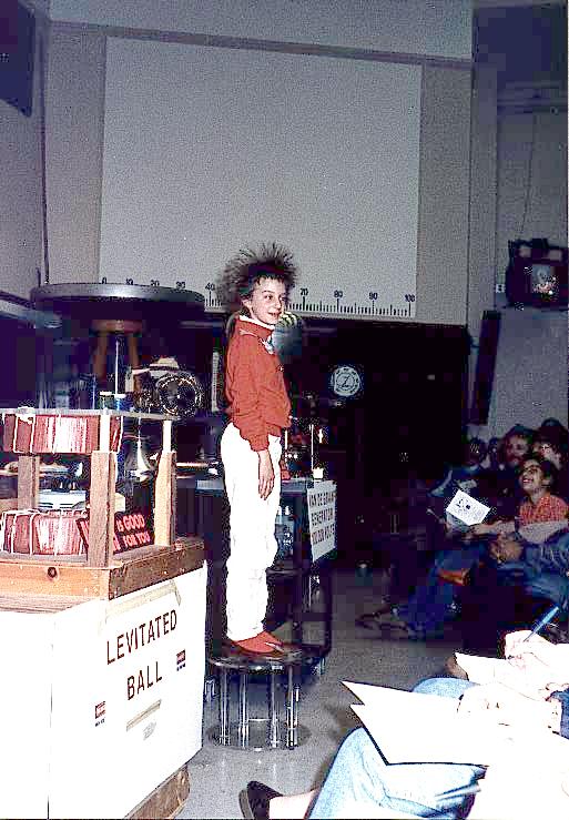
The standard demonstration involves having a volunteer stand on an insulated stool (of a height greater than the diameter of the dome to ensure adequate insulation) and place a hand on the dome while the Van de Graaff generator is turned on. After a few minutes, the volunteer's hair will begin to stand on end. A hand mirror is useful to allow the person to see what is happening (but don't hand it to someone charged to high voltage!). A Polaroid photograph also makes a good souvenir.
It is best to choose someone with medium length, fine, dry hair. Shaking the head helps make the hair stand up. The person should be well away from any grounded conductors and told to leave the hand on the dome at all times until told to remove it. When finished, the dome should be slowly discharged by bringing a grounded, pointed needle near the dome while the person is still in contact with it. The hair will drop back into place as corona from the needle discharges the dome, and the volunteer can then step down from the stool. The stool should be cleaned before use. If the stool is at all tipsy, the person should be given help up and down.
Afterwards, one could show the distance over which a spark can be made to jump by bringing a grounded sphere near the dome. The increased capacitance of the sphere makes the spark more intense and visible. If the grounded sphere is mounted on a flexible rod, the attractive force due to the induced charge in the sphere will make the support rod bend toward the dome. When a spark occurs, neutralizing the charge on the grounded sphere, the support rod will straighten, producing a mechanical vibration.
Other demonstrations can also be done with the Van de Graaff generator. Puffed rice placed on the dome will fly off in all directions when the generator is turned on. A pinwheel placed on the dome can be made to rotate from the corona given off the points. A fluffy cotton ball or silvered balloon[7-9] released near the generator will be attracted to the dome and then repelled after it touches the dome and becomes charged with the opposite polarity. Soap bubbles can be blown toward the dome by someone at ground potential or away from the dome by someone touching the dome[10,11]. Bits of fur can be tossed into the region between a charged and grounded dome and illuminated with a strong light to illustrate qualitatively the shape of the electric field[12].
2. A. D. Moore, ed., Electrostatics and its Applications, John Wiley & Sons: New York (1973).
3. H. Walton, Popular Science 185, 142 (1964).
4. E. Francis, Popular Electronics 24, 57 (1966).
5. C. L. Strong, Scientific American 225, 106 (Aug 1971).
6. L. B. Loeb, Electrical Coronas, University of California Press: Berkeley, CA (1965).
7. P. Hood, Am. Journ. Phys. 14, 445 (1946).
8. A. V. Baez, Am. Journ. Phys. 25, 301 (1957).
9. M. D. Daybell and R. J. Liefeld, Am. Journ. Phys. 31, 135 (1963).
10. G. R. Gore, Science Teacher 39, 48 (1972).
11. R. Prigo, Am. Journ. Phys. 44, 606 (1976).
12. J. L. Smith, Phys. Teach. 27, 358 (1989).
13. P. H. Rose and A. B. Wittkower, Scientific American 223, 24 (Aug 1970).
14. A. D. Moore, Electrostatics: Exploring, Controlling & Using Static Electricity, Doubleday: New York (1968).
 The Tesla coil is a type of resonant transformer that is capable of producing
high frequency voltages of upwards of a million volts. The Tesla coil was
developed by Nikola Tesla (1856-1943), a contemporary and rival of Thomas
Edison (1847-1931). Tesla's biography makes especially interesting reading[1-4].
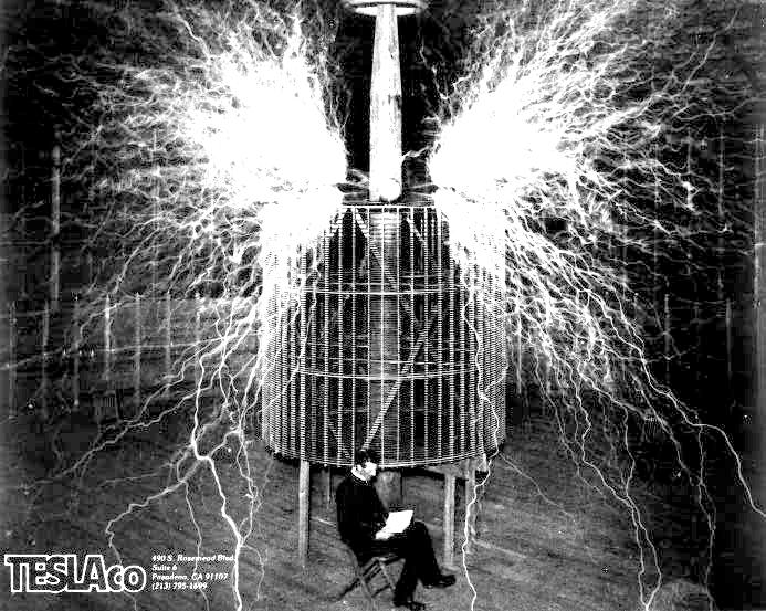
In 1899 Tesla produced 135 foot long discharges, 200 feet above the earth
with a 12 million volt coil at his Colorado Springs laboratory, and the
overload on the power line set fire to the alternator of the Colorado Springs
Electric Company. Tesla imagined using his invention not only for wireless
communications around the world but also for the widespread dissemination
of electric power without the use of wires.
The Tesla coil is a type of resonant transformer that is capable of producing
high frequency voltages of upwards of a million volts. The Tesla coil was
developed by Nikola Tesla (1856-1943), a contemporary and rival of Thomas
Edison (1847-1931). Tesla's biography makes especially interesting reading[1-4].
In 1899 Tesla produced 135 foot long discharges, 200 feet above the earth
with a 12 million volt coil at his Colorado Springs laboratory, and the
overload on the power line set fire to the alternator of the Colorado Springs
Electric Company. Tesla imagined using his invention not only for wireless
communications around the world but also for the widespread dissemination
of electric power without the use of wires.
Because of its high frequency, the Tesla coil provides a relatively safe way to demonstrate very high voltage phenomena. A large Tesla coil is probably the most spectacular of all electrical demonstrations. The Tesla coil also makes an excellent student project since there is much room to experiment and to optimize its performance. The followers of Tesla almost constitute a cult. There is an International Tesla Society** and a Tesla Coil Builders Association*** that publishes a journal containing much useful information. Old issues of electronic hobby magazines[5-10], scientific journals[11-14] and books[15-17] have construction details. A recent book that contains much practical design information is Modern Resonance Transformer Design Theory, by D. C. Cox.****
**International Tesla Society, 330-A West Uintah Street, Suite 215, Colorado Springs, CO 80905-1095 (303) 570-0875
***Tesla Coil Builder's Association, 3 Amy Lane, Queensbury, NY 12804 (518) 792-1003
****Available from Resonance Research, Corp. R1, Shadylane Rd., Box 320A, Baraboo, WI 53913 (608) 356-3647. This company also produces custom-made Tesla coils and other electrical demonstration apparatus.
There are many other possible uses for the Tesla coil aside from producing long and impressive sparks in the air surrounding the top of the coil. It should be possible to illuminate a fluorescent or gas-filled tube held in the hand some distance away. A hydrogen-filled balloon on the end of an insulated rod can be made to explode when brought near the top of the coil. It is possible to draw the current through one's body by bringing a long metal rod held in the hand near the top of the coil. With a large coil one should be able to light an incandescent bulb in series with the rod. One should use the highest voltage bulb possible to get the most light for a given current. If a sufficiently well-insulated platform is available, one should be able to stand with bare feet on a metal plate (or more impressively sit in a washtub full of water) connected by a wire to the top of the coil and light a discharge tube or clear incandescent light bulb held in the hands or draw sparks off the tips of the fingers. In doing this demonstration, the hair should be wetted and metal thimbles worn on the fingers to prevent burns.
The Tesla coil is essentially a radio transmitter without the antenna, and thus Tesla rightly deserves some of the credit for the invention of the radio, although his interest was more in the transmission of electric power than in communication. It is capable of producing severe radio interference and thus should be operated inside a shielded cage and only for brief intervals. A suitable detector, such as a large loop of wire with a pair of conducting balls on the ends between which sparks can jump, placed some distance from the coil, demonstrates the propagation of these radio waves. One can also point out that the discharge is a good example of a fractal.
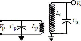 The Tesla coil
consists of primary and secondary resonant circuits tuned to the same frequency
(f = 1/2(pi)(LC)½) of the order of 100 kHz to 1 MHz and
designed to have the highest possible Q (lowest circuit loss). The secondary
capacitance Cs is predominantly distributed capacitance due
to the proximity of adjacent windings, and thus the secondary behaves much
like an open circuit transmission line with a resonance whenever the electrical
length is an odd multiple of a quarter wavelength. The Tesla coil is normally
designed to operate at the lowest resonant frequency of the secondary to
avoid a voltage maximum other that at the top of the secondary coil. If
the coupling between the primary and secondary is adjusted to be near the
critical value (kQ ~ 1), then the secondary voltage is given approximately
by Vs = Vp(Ls/Lp)½
independent of the turns ratio. In practice one would normally construct
the secondary coil and then adjust Cp, Lp and the
coupling constant k to give the largest Vs for a given Vp.
The Tesla coil will have to be retuned depending upon what is connected
to the secondary. Taps on the primary are useful for this purpose.
The Tesla coil
consists of primary and secondary resonant circuits tuned to the same frequency
(f = 1/2(pi)(LC)½) of the order of 100 kHz to 1 MHz and
designed to have the highest possible Q (lowest circuit loss). The secondary
capacitance Cs is predominantly distributed capacitance due
to the proximity of adjacent windings, and thus the secondary behaves much
like an open circuit transmission line with a resonance whenever the electrical
length is an odd multiple of a quarter wavelength. The Tesla coil is normally
designed to operate at the lowest resonant frequency of the secondary to
avoid a voltage maximum other that at the top of the secondary coil. If
the coupling between the primary and secondary is adjusted to be near the
critical value (kQ ~ 1), then the secondary voltage is given approximately
by Vs = Vp(Ls/Lp)½
independent of the turns ratio. In practice one would normally construct
the secondary coil and then adjust Cp, Lp and the
coupling constant k to give the largest Vs for a given Vp.
The Tesla coil will have to be retuned depending upon what is connected
to the secondary. Taps on the primary are useful for this purpose.
The input voltage Vp can be produced in a number of ways. The usual way is to connect the input through a rotary spark gap to the secondary of a high voltage (several kV) transformer connected to the ac power line through a current-limiting inductor. The opening and closing of the rotary gap (typically a few hundred pulses per second) creates a ringing voltage waveform after each opening. The spark gap and transformer can also be inserted in series between Cp and Lp to create a ringing waveform after each closing of the switch. The acoustically noisy spark gap can be replaced with a thyratron or ignitron and triggered from a source that is phase-locked to the 60 Hz power line. The voltage Vp can also be derived from a high voltage, vacuum tube oscillator circuit.*****
*****See an old issue of The Radio Amateur's Handbook, published yearly by the American Radio Relay League: 225 Main Street, Newington, Connecticut 06111.
If the Tesla coil is used to light a fluorescent tube, care should be taken to avoid breaking the tube. The powder that lines the inner walls of such tubes as well as the mercury that they contain are highly poisonous.
2. I. Hunt and W. W. Draper, Lightning in his Hand: The Life Story of Nikola Tesla, Sage Books: Denver (1964).
3. T. C. Martin, The Inventions, Researches and Writings of Nikola Tesla, Omni Publications: Hawthorne, California (1977).
4. J. J. O'Neill, Prodigal Genius: The Life of Nikola Tesla, Neville Spearman: London (1944).
5. L. Reukema, Experimenter 4, 309 (1925).
6. R. C. Dennison and E. H. McClelland, Electrical Journal 28, 328 (1931).
7. K. Richardson, Popular Electronics 12, 72 (1960).
8. C. Caringella, Popular Electronics 21, 29 (1964).
9. E. Kaufman, Popular Electronics 21, 33 (1964).
10. V. Vollano, Popular Electronics 71, 29 (1989).
11. G. Breit and M. A. Tuve, Nature 121, 535 (1928).
12. G. Breit, M. A. Tuve, O. Dahl, Phys. Review 35, 51 (1930).
13. C. R. J. Hoffmann, Review of Scientific Instruments 46, 1 (1975).
14. I. Boscolo, G. Brautti, R. Coisson, M. Leo, A. Lunches, Review of Scientific Instruments 46, 1535 (1975).
15. H. S. Norris, Induction Coils - How to Make, Use, and Repair Them, Spon and Chamberlain (1909).
16. G. F. Haller and E. T. Cunningham, Tesla High Frequency Coil - Its Construction and Uses, D. Van Nostrand Co.: New York (1910).
17. A. D. Bulman, Models for Experiments in Physics, Crowell Co.: New York (1966).
The most spectacular demonstration is to put a person inside a grounded Faraday cage and turn on a large Tesla coil or Van de Graaff generator outside the cage. It is especially good to have a celebrity known to the audience enter the cage. The discharge from the Tesla coil or the sparks from the Van de Graaff generator strike the cage but do not hurt the person inside. The person inside can hold a fluorescent tube which will not light and can even touch the inside of the cage without harm. The electric currents flow on the outside of the cage, and the interior of the cage is all at the same electric potential. The person should not stick a finger or other object through a hole in the cage, however. If someone in the front row is given a fluorescent tube, it can be made to light while the one in the cage does not. After the demonstration, one can point out that the person in the cage was in fact safer than those in the front row.
With a sufficiently well-constructed Faraday cage, it should be possible to put a portable transistor radio inside and not be able to receive any radio stations on either the am or fm bands. To do this requires all the seams to be tightly sealed electrically and the holes in the conductor not to be too large. This provides a sensitive way to test the quality of the Faraday cage.
With a sufficiently large Van de Graaff generator or Tesla coil and an insulated platform for the cage to rest on, it is possible to raise the voltage of an ungrounded cage to a high level with a person inside. Metallic tinsel such as used to decorate Christmas trees when attached to the outside of the cage will stick out like the hair of a person on a Van de Graaff generator, but similar tinsel inside the cage will show no response.
The Faraday cage is named after Michael Faraday (1791-1867), a self-educated, English physicist and chemist whose lectures for the public in the 1840's became so popular that they helped save the Royal Institution of Great Britain from near bankruptcy[1]. His lectures were attended by Charles Dickens and by Prince Albert, the husband of Queen Victoria, and Prince Edward, her son (later Edward VII). In 1826 Faraday also began a series of immensely popular, special Christmas lectures for children which have continued up to the present. Since 1966, these lectures have been televised and broadcast throughout Britain.
*Available from Carolina Biological Supply Company, Central Scientific Company, Frey Scientific Company and Sargent-Welch Scientific Company
The tube is initially filled with air at atmospheric pressure, and the voltage is applied. Normally, there will be no glow from the tube and no current drawn. As the tube is slowly evacuated, a pressure is reached at which current abruptly begins to flow, and sparks are seen emanating from the electrodes. As the pressure is further reduced, a steady violet glow will appear throughout the tube. At even lower pressure, alternating light and dark bands (Crookes and Faraday dark spaces) can be seen along the length of the tube, until eventually the glow is completely extinguished. Note that the striations are always convex toward the cathode. The pump can then be turned off, and the progression repeated in reverse as air is bled back into the tube. The demonstration can then be repeated with other nonflammable gases such as neon, carbon dioxide and argon. Each will produce a glow with a distinctive color characteristic of the gas. A magnet placed near the discharge can be used to effect its shape. It can be pointed out that a glow discharge tube does not obey Ohm's law.
This demonstration can serve as an introduction to the subject of plasma physics[5]. Plasmas represent the fourth state of matter, along with solids, liquids and gases. Plasmas represent the end result of raising the temperature of any substance, most of which transform successively through each of the four states. Plasmas differ from ordinary gases in that they are electrical conductors, a difference that is as remarkable as the differences among the other three states. Plasmas are relatively rare on the earth but constitute upwards of 99% of the matter in the universe. Examples of plasmas in nature include the Aurora Borealis, the ionosphere of the earth, the solar wind and the material of the sun and stars. Laboratory plasmas are of great current interest because certain atoms such as isotopes of hydrogen at temperatures in excess of 100 million degrees will release energy by the process of nuclear fusion, a potentially clean and abundant source of energy[6,7].
2. C. L. Strong, Scientific American 198, 112 (Feb 1958).
3. B. Z. Shakhashiri, Chemical Demonstrations, The University of Wisconsin Press: Madison, Wisconsin, Vol 2 (1985).
4. H. F. Meiners, W. Eppenstein, R. A. Oliva and Thomas Shannon, Laboratory Physics, John Wiley & Sons: New York (1987).
5. F. F. Chen, Introduction to Plasma Physics, Plenum Press: New York (1984).
6. A. S. Bishop, Project Sherwood, Addison-Wesley Publishing Company: Reading, Massachusetts (1958).
7. T. K. Fowler and R. F. Post, Scientific American 215, 21 (Dec 1966).
2. M. Robinson, Am. Journ. Phys. 30, 366 (1962).
3. M. Robinson, Bibliography of Electrostatic Precipitator Literature, Southern Research Institute: Birmingham, Alabama (1969).
4. F. T. Cameron, Cottrell, Samaritan of Science, Doubleday: Garden City, New York (1952).
5. H. J. White, Industrial Electrostatic Precipitation, Addison-Wesley: Reading, Massachusetts (1963).
6. A. D. Moore, ed., Electrostatics and its Applications, John Wiley & Sons: New York (1973).
7. J. Bohm, Electrostatic Precipitators, Elsevier Scientific Publishing Company: New York (1982).
8. J. S. Miller, Physics Fun and Demonstrations, Central Scientific Company: Chicago (1974).
9. W. R. Mellen, Phys. Teach. 27, 86 (1989).
                          Sphere Diameter (cm)
     kV        2.5       3.0       4.0       5.0       10.0

     10        0.30      0.30      0.30      0.30      0.30
     20        0.61      0.61      0.61      0.61      0.61
     30        0.95      0.95      0.95      0.95      0.95
     40        1.40      1.32      1.30      1.30      1.30
     50        2.00      1.82      1.73      1.71      1.65
     60        2.81      2.40      2.21      2.16      2.02
     70        4.05      3.16      2.80      2.68      2.41
     80                  4.40      3.50      3.26      2.82
     90                            4.40      3.93      3.28
    100                                      4.76      3.75
The stored electrical energy is CV2/2 or about 1920 joules when the 60-µF capacitor is charged to 8 kV. This can be likened to a 50-kg person raised 3.9 meters into the air, or the energy in about 8 food calories.
[Next Chapter] [Previous Chapter] [Introduction] [Server Home]
J. C. Sprott